Electronics are Still a Mistry
I wrote a post a few weeks ago about, my electronics project and I promised an update. The board arrived and I soldered in just enough for testing, I didn’t solder in all eight inverters, just the one. I did solder in a RJ9 so I could connect one of the hall affect sensors. With five volts kind of a hacked in and a neodymium magnet I was able to test and check the Active Invertor which did exactly as i needed.
I then soldered in the components for the Buck converter, and again supplying 5volts to 24volts the converter reduced the voltage flow to 4.98V, 5Volts through out the range.
At this point I can say that the porotype board did exactly what i needed. Here is the crunch though the Buck Converter components were only rated to 1.5Amps and when adding up all of the required ampage, I needed 3.2amps.
So back to the drawing board…
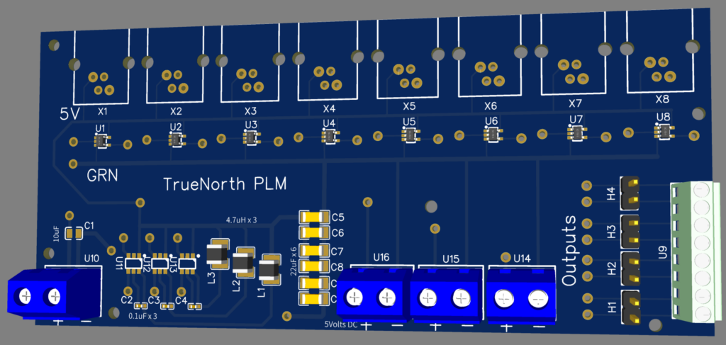
I looked through all of the parts online but I could not find anything that would cover 3.2amps. So I decided to put the original Buck Converter in but this time 3 of them in parallel. I have no idea if this will work, but the logic seems correct, that each one will divide the draw ampage across them selves giving a total capacity of 4.5Amps. This should be more than enough capacity for my needs, so below is the new board design. I was able to maintain the same package space as the prototype board but squeeze in 2 additional Buck Convertors.
I’m waiting for the board to arrive and this time I ordered a Mask to aid with the soldering, I have realized that with age my eye sight has faded a little and I’m no longer capable of applying the tiny tiny amounts of solder paste repaired per coper area.
That’s my update, I hope this finds you all well.