Electronics its a Mistry
I have been building or owned CNC machines for a while, the mechanics piece is great especially if you have a 3D printer and some time. The electronics piece is fairly easy there is lots of information and i can plug a wire from point A to point B easily enough but when it comes to the mystery art of IC’s, Resistors and Capacitors that where things get really fuzzy.
Hall affect Sensors
One thing that drives me mad is the misuse of limit switches, many times you see that designers just slam a moving component into the limit switch, they are supposed to be gently lifted as a moving component moves past the switch a bit like a cam. When i built my first CNC kit from X-Carve i deleted the limit switches and purchased some Hall Affect sensors from a maker. Unfortunately one broke and the original maker was no longer in business so i reverse engineered it.
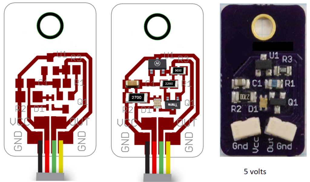
Using EasyEDA this is what I came up with.
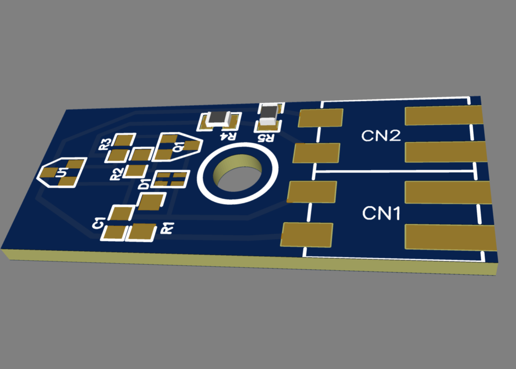
I had JLCPCB make a small batch run of 20 and they work great, and you can order from them directly thought the EasyEDA software.
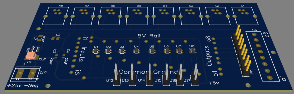
Controller Board
My next challenge which happened a few weeks ago is the controller board that connects to these sensors died. This is what i came up with, below I will go through each piece.
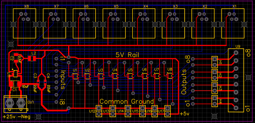
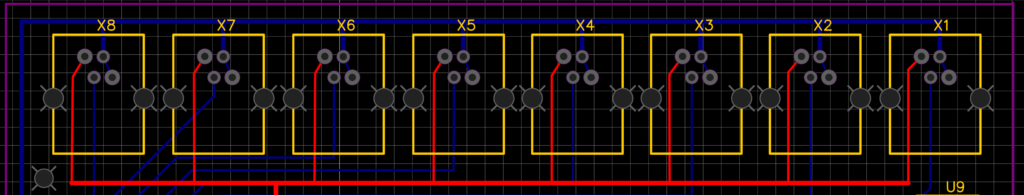
To connect the sensors to the board I added 8 RJ9 connectors which have four pins X1 -> X8.
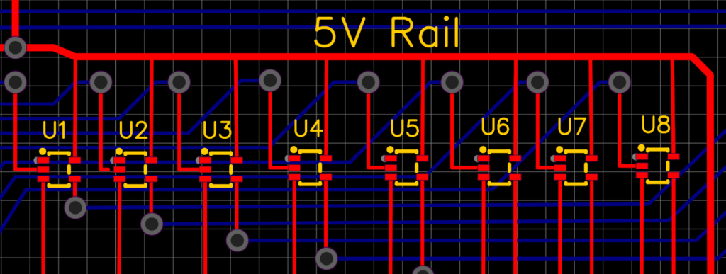
The board inverts the Normally Closed Signal from the sensors to a Normally Open one for the CNC controller. To do this I added 8 Active Invertors U1-> U8 that will take in a 5V signal and output a 0V signal or visa-versa.
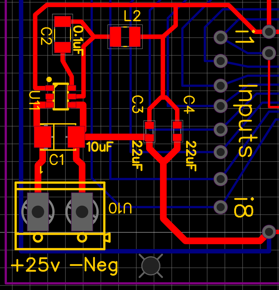
I also wanted to add some additional functionality, currently I have a separate 5volt power supply. So want to add a Buck convertor to the board to take 25Volts from the main power supply and step it down to 5volts.
Additionally, I also wanted to be able to combine two outputs into one so i could have X+ and X- limits or Y+ and Y- limits send a single signal to the CNC controller, so I added jumpers H1->H4 to allow that.
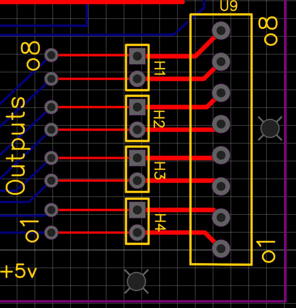
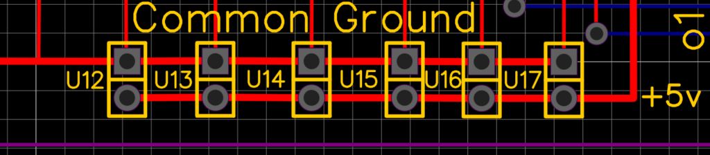
Finally, i wanted to have some 5V output connections for LED’s and other things so I added a row of 5V and ground pins, U12 -> U17.
I ordered the board and the electronic components from JLCPCB, and the components to go on the board so once it arrives i will give you an update.