Table of Contents
CAD Replicating Features on a Complex Surface
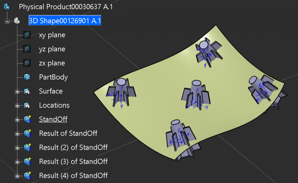
In this example we need to replicate the design feature to the other four locations, we could just redesign it which would be a lot of work. We could create a Power Copy and quickly replicate the feature to the other positions, but if we needed to make a change we would have to make the same change five times. We could make a User Defined feature, and instantiate it five times, then change the exposed parameters which would expedite design changes.
In this case were going to use Internal links to ensure we only have one source of truth.
Feature Setup
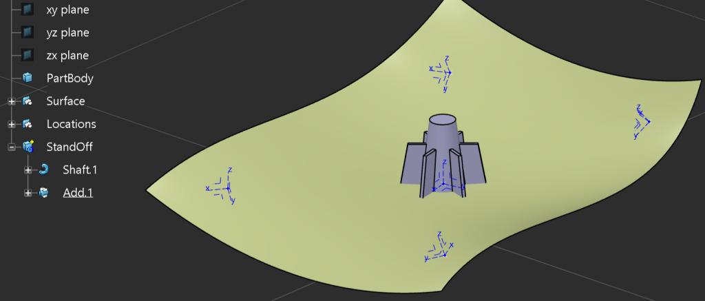
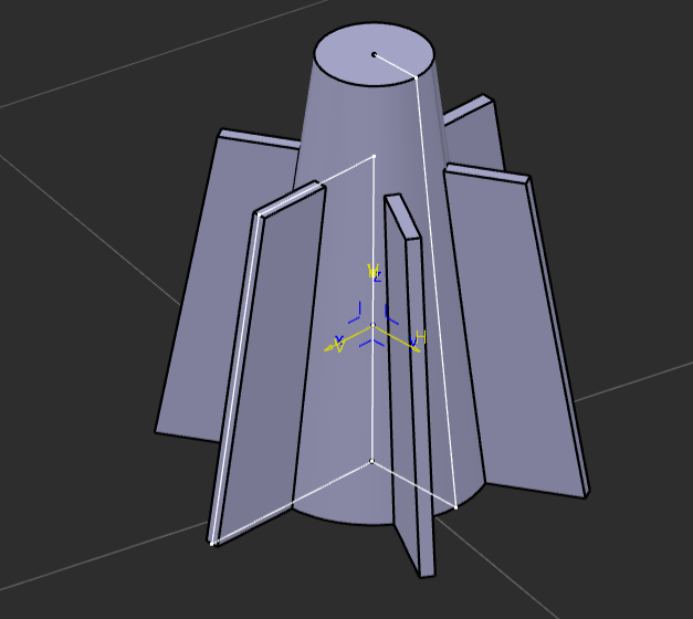
To do this correctly it’s important to base the features design on an axis system. As you can see the sketches that define this feature are supported by the Axis System planes.
Copy and Paste with Link
Let’s start of with one and the rest will be the same process.
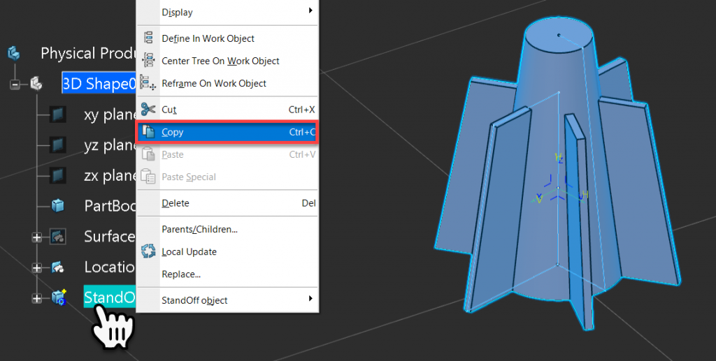
Right Mouse Click on the Feature Body and select Copy from the contextual menu.
Right Mouse Click on ‘Shape’ and select Paste Special from the contextual menu.
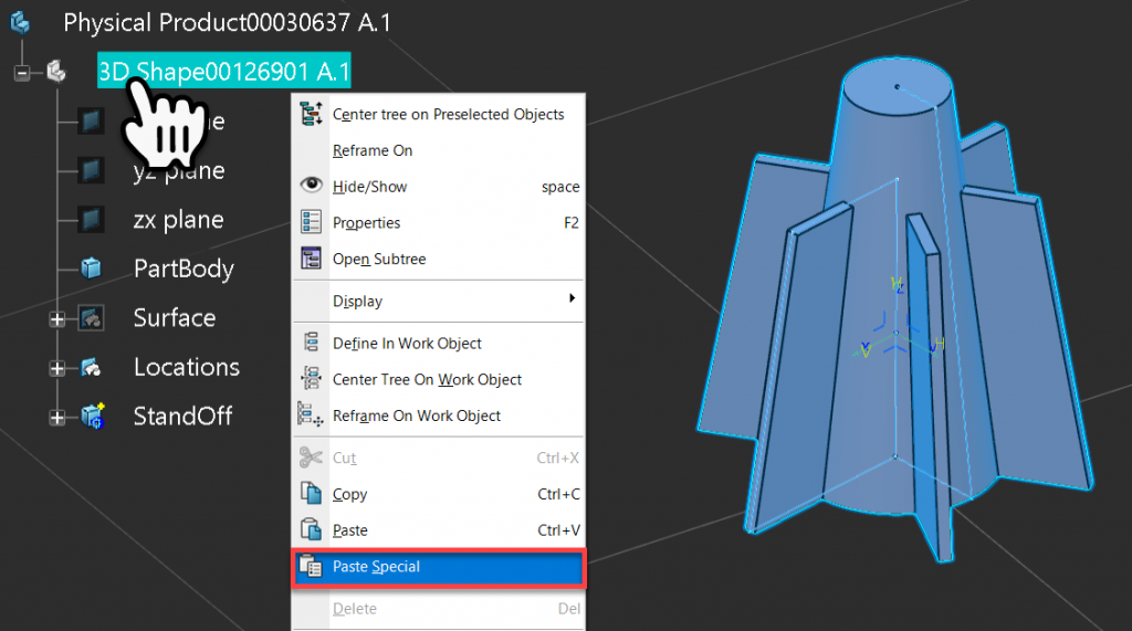
In the ‘Paste Special’ dialogue window select As Result With Link, the pick ‘Ok’ to complete the command.
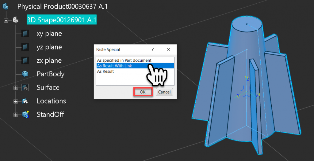
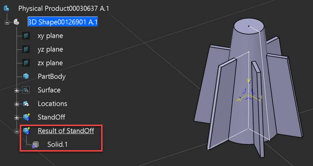
We now have an internally linked copy of the feature but its in the wrong location. We could do an axis to axis transformation, but this hides the copy and creates a clone in the new location, for small features you could argue this is ok. However for larger features this has a huge impact on data size and should be avoided at all cost, so we will look at a cleaner solution.
Adding Position
We can use the ‘Add Position’ method to correctly locate the linked copy of the feature. This is achieved by Right Mouse Clicking on the linked solid ( Not the Body) and selecting Add Position from the contextual menu.
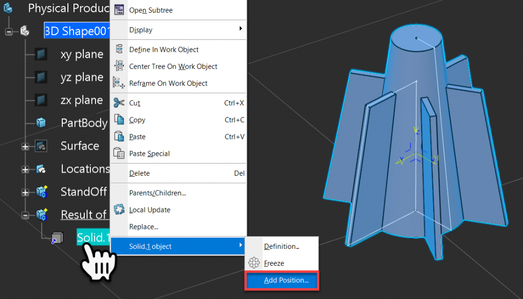
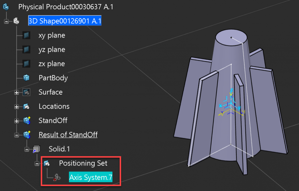
This function will create a special Geometrical Set below the linked solid called ‘Positioning Set’. Within the Positioning Set a ‘Datum’ (Isolated) Axis System is created at the Center of Gravity of the Solid and Orthogonal to the Part. This is just a placeholder and can be replaced with our own axis system, to ensure a good parametric solution.
This process is basically identical to the Axis to Axis transformation we need to supply the ‘From’ and the ‘To’ Axis Systems into the Add Position geometrical set. We have two choices, we can either move the Axis Systems into the Positing Set for each instance (but we only have one ‘From’ Axis System), or we can use internal links again. For this example we will use internal links.
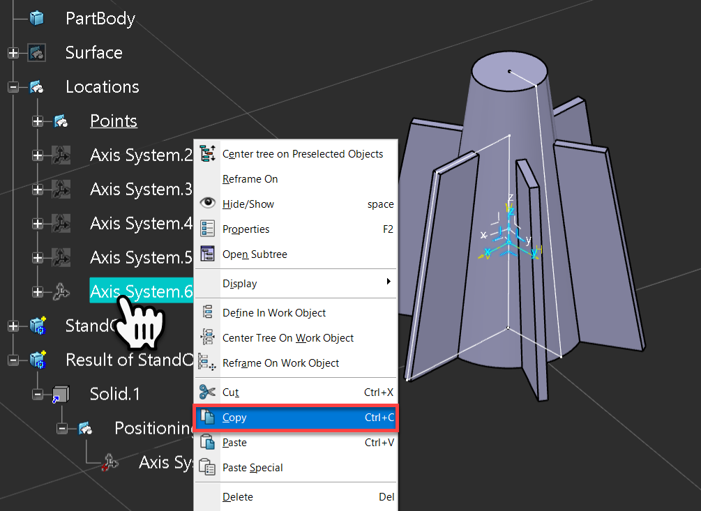
Let’s Copy the Axis System that the initial feature was design on.
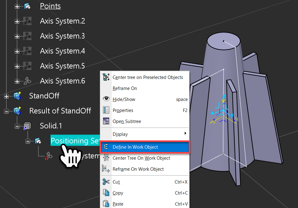
There is an odd behavior with the ‘Positing Set’, we can’t just Paste Special Directly into the Positing Set, we have to ensure that it’s the Defined In Work Object first. To do this Right Mouse Click on the ‘Positing Set’ and select Define In Work Object from the contextual menu.
Again Right Mouse Click on the ‘Positing Set’ and select Paste Special from the contextual menu.
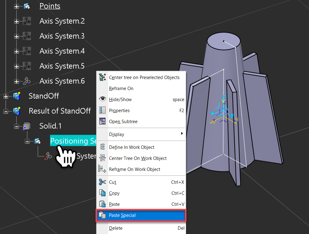
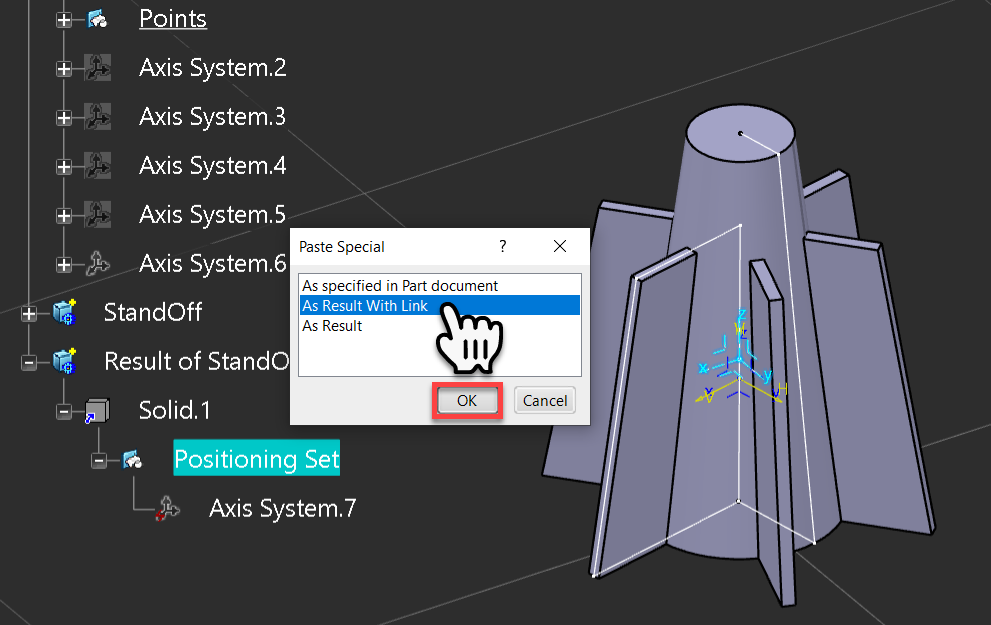
In the ‘Paste Special’ dialogue window select As Result With Link, the pick ‘Ok’ to complete the command.
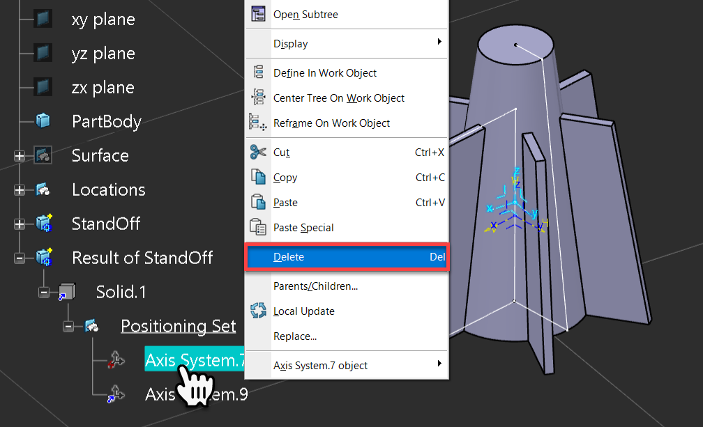
We now have a linked copy of the Reference Axis System, the next step is to delete the Axis System the CAD system created for us.
To Delete the Axis System, Right Mouse Click on it and Select Delete from the contextual menu.
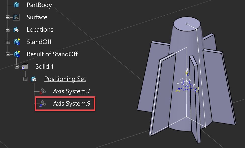
Using the same steps we can create a linked copy of the Target Axis System. Once the Defined In Work Object is set to the Copied Body, the Re-Positioned copy can be seen.
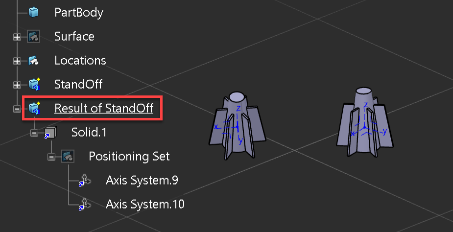
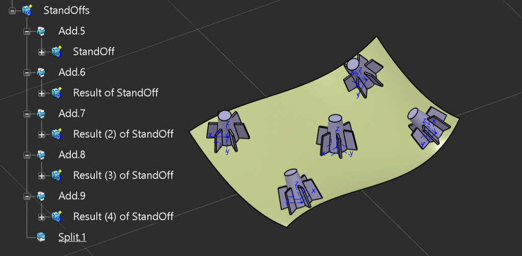
We can repeat the process for the other three locations, as shown below:
The final step is to group these feature branches into a single feature branch. To do this a new body was inserted and the five features added to it. Then a single split operation was created to trim the features to the supporting surface. It’s best practice to ensure that the first feature added is the feature that contains the definition for the feature and not one of the four linked copies.