Table of Contents
EKL Managing Surface Orientation
When we create geometry or consume geometry from another part, we have no idea what the Surface Normal orientation is, but who cares? If it’s our own geometry in our own part we tend not to care too much and live with the consequences during modification, and most of the time we don’t stop to think about why the child geometry offset the wrong way, we just fix it.
When it comes to geometry consumed from another part we tend to care a little more, but we never stop to ask why did the Surface Normal change, and again we just fix the problem. This is probably because it’s completely out of our own control, it’s somebody else’s geometry.
I’m going to show you how to control the Surface Normal’s orientation automatically.
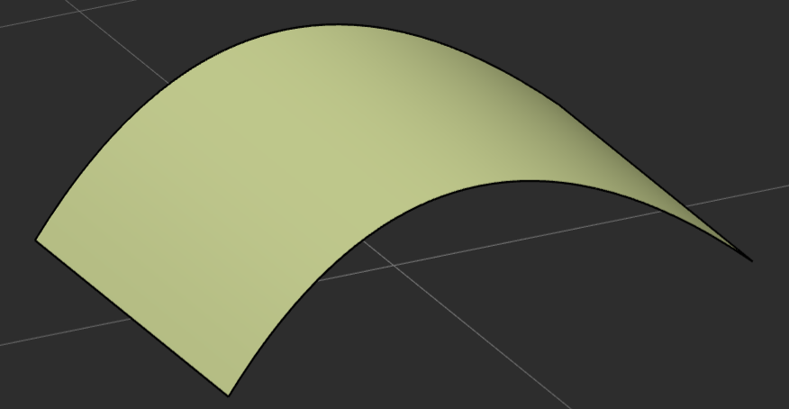
If we look at this surface we can’t tell easily what it’s Normal orientation is, but we can use some simple geometry functions to do this.
Manually Controlling the Surface Normal
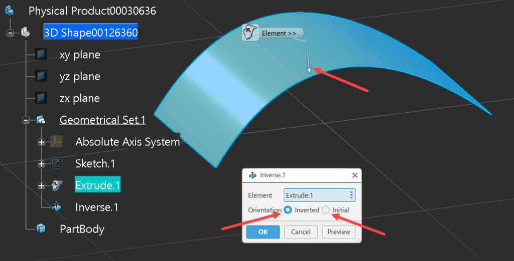
Most CAD systems have the capability to invert a surface, this is not the same as changing the offset side during an offset operation or any other type of operation. The Invert creates a clone of the surface and inverts it’s Normal direction. In the case below we can see that the Invert operation shows us the resulting Surface’s Normal orientation and gives us the capability to reset it to the ‘Initial’ extruded Surface’s Normal orientation.
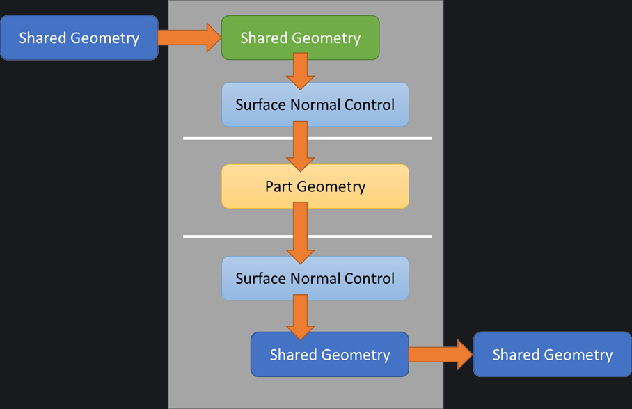
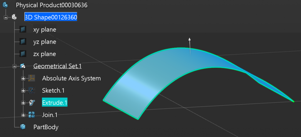
The other operation that can be used to visualize the Surface’s Normal orientation is the Join function. It’s used to concatenate many surface(s) together. When the ‘Preview’ button is selected the Surface’s Normal orientation is shown but not inverted. We can use either of these two geometrical functions as an additional step, either after creating a complex surface or consuming a surface from another part. This way, if the Surface’s Normal is inadvertently changed we have a geometrical step where we can intervene.
When creating key design surfaces in a design it’s always a good idea to create a join directly afterwards, because a Surface’s Normal can be inverted accidently by modifying the underlying geometry. For example, drawing a new profile clockwise, instead of anti-clockwise, and not using the replace function. Another opportunity for a Surface Normal to be changed during a parts update is due to angular inversion. This happens when the angle between two lines, for example, changes from 170 degrees to 190 degrees. If there was a plane generated from the two lines, its normal orientation will be flipped, then this change would cascade down the child parent relationships into the surface and may invert its Normal. So how do we control this automatically?
Automatically Controlling the Surface Normal
When looking at the topology of the surface, we can group the surface into one of two groups; Continuously (but not necessarily constant) Positive or Negative curvature, or Planar / S-Shaped. If the surface falls into the first category, for example a leading edge wing surface, we can automatically control it’s Normal by using the offset surface area rule.
Let’s look at some pseudo code to understand this:
Start:
  Get the Input Surface

  Create a 1mm offset of the Input Surface

  If the Surface Area of the input Surface is larger than the offset Surface
      Return the Input Surface
  Else
      Return an Invert of the Input Surface
End:
Below is a working example of this, but we are hard coding the fact that we always want the Surface Normal to point outwards from the curvature of the surface. We could manually edit the code and change the greater than symbol to less than, but who wants to do this?
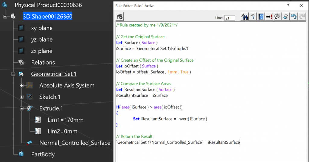
Completed Code.
/*Rule created by me 1/9/2021*/

// Get the Original Surface
Let iSurface ( Surface )
iSurface = `Geometrical Set.1\Join.1`

// Create an Offset of the Original Surface
Let ioOffset ( Surface )
ioOffset = offset( iSurface , 1mm , True )

// Compare the Surface Areas
Let iResultantSurface ( Surface )
iResultantSurface = iSurface

If( area( iSurface ) > area( ioOffset )) {
	Set iResultantSurface = invert( iSurface )
}

// Return the Result
`Geometrical Set.1\Normal_Controlled_Surface` = iResultantSurface
Allowing the user to Define the Surface Normal Orientation
So let’s take it one more step further. We have added a simple Boolean parameter that when set to true the Surface Normal will point outward from the surface’s curvature, and when set to False will point inwards towards the surface’s curvature. Then, in the code we expanded the ‘If Statement’ to handle the parameter. Now the user has the capability to choose which side should maintain the Surface Normal (we can see this in the video below).
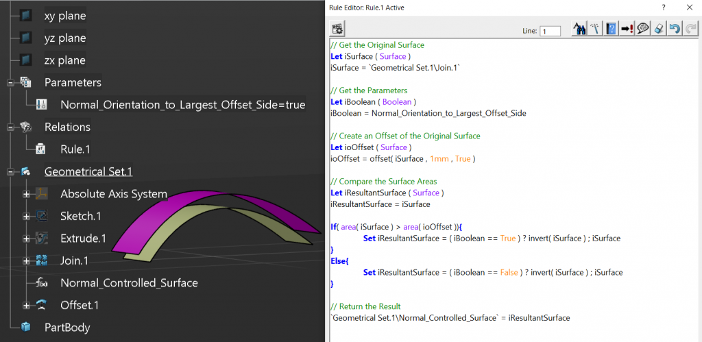
The video shows that when the Surface Normal of the Join is changed, the offset will maintain its offset direction until the user changes the parameter from ‘True’ to ‘False’, or vice-versa.
Completed Code.
/*Rule created by me 1/9/2021*/

// Get the Original Surface
Let iSurface ( Surface )
iSurface = `Geometrical Set.1\Join.1`

// Get the Parameters
Let iBoolean ( Boolean )
iBoolean = Normal_Orientation_to_Largest_Offset_Side

// Create an Offset of the Original Surface
Let ioOffset ( Surface )
ioOffset = offset( iSurface , 1mm , True )

// Compare the Surface Areas
Let iResultantSurface ( Surface )
iResultantSurface = iSurface

If( area( iSurface ) > area( ioOffset )){
	Set iResultantSurface = ( iBoolean == True ) ? invert( iSurface ) ; iSurface
}
Else{
	Set iResultantSurface = ( iBoolean == False ) ? invert( iSurface ) ; iSurface
}

// Return the Result
`Geometrical Set.1\Normal_Controlled_Surface` = iResultantSurface
Semi-Automatically Controlling the Surface Normal
Let’s now look at the other group where the surface is either Planar or S-Shaped. This is a little harder as an offset surface will have the same surface area, so we have to add a reference geometry to aid in determining the Surface Normal orientation. For the reference geometry a good place to start is the center of gravity of the surface. This tends to be one side or another, otherwise you could use a point on the vehicle’s center line plane or on an adjoining part.
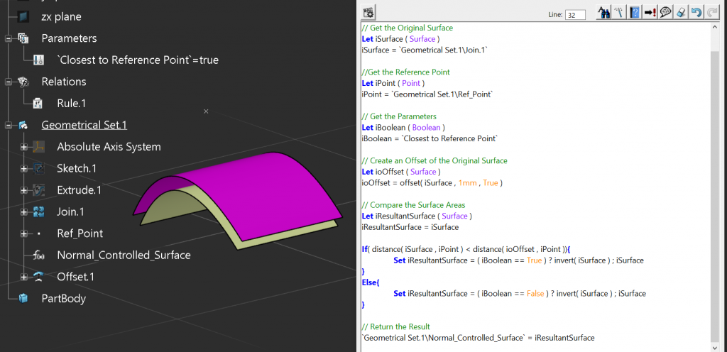
In the video below we can see that the Surface’s Normal is controlled by the Reference Point. And again, as before, if we changed the Surface Normal by editing the Join operation, this would have no affect on the Surface’s Normal orientation. It’s purely driven by the Reference point.
Completed Code.
/*Rule created by me 1/9/2021*/

// Get the Original Surface
Let iSurface ( Surface )
iSurface = `Geometrical Set.1\Join.1`

// Get the Sample Point
Let iPoint ( Point )
iPoint = `Geometrical Set.1\Ref_Point`

// Get the Parameters
Let iBoolean ( Boolean )
iBoolean = `Closest to Reference Point`

// Create an Offset of the Original Surface
Let ioOffset ( Surface )
ioOffset = offset( iSurface , 1mm , True )

// Compare the Surface Areas
Let iResultantSurface ( Surface )
iResultantSurface = iSurface

If( distance( iSurface , iPoint ) < distance( ioOffset , iPoint )){
	Set iResultantSurface = ( iBoolean == True ) ? invert( iSurface ) ; iSurface
}
Else{
	Set iResultantSurface = ( iBoolean == False ) ? invert( iSurface ) ; iSurface
}

// Return the Result
`Geometrical Set.1\Normal_Controlled_Surface` = iResultantSurface
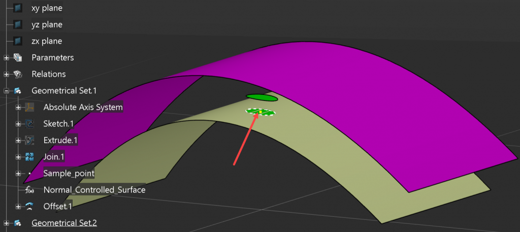
Managing Complex Surfaces
We’ve all created surfaces that don’t like to be offset, so how do we handle this case? Normally somewhere on the surface is a simpler area, so we can leverage the inheritance rule to our advantage. We know if we were to cut out a little piece of the surface, the resulting surface would inherit the parents Surface Normal orientation. So we can change our code to consume a point on the surface that then creates a small circular sample of the surface with a 1mm radius. We will then test this surface by offsetting it and applying the result back to the parent surface. Again, the surface must have a different surface area when it’s offset so the sample point cannot be on a planar portion of the complex surface.
In the image below I have also shown the sample point and the resulting sample patch and offset.
Complete Code…
/*Rule created by me 1/9/2021*/

// Get Test Geometrical Set
Let ioTestGeoSet ( OpenBodyFeature )

// Get the Original Surface
Let iSurface ( Surface )
iSurface = `Geometrical Set.1\Join.1`

// Get the Parameters
Let iBoolean ( Boolean )
iBoolean = `Maintain Normal to Largest Surface Area`

// Get the Sample Point
Let iPoint ( Point )
iPoint = `Geometrical Set.1\Sample_point`

// Create the Sample Patch
Let ioPlane ( Plane )
ioPlane =planetangent( iSurface , iPoint )

Let ioCircle ( Circle )
ioCircle = circleCtrRadius( iPoint , ioPlane , 1mm , 1 , 0deg , 180deg )

Let ioProject ( Curve )
ioProject = project( ioCircle , iSurface , NULL )

Let ioSplitSurface ( Surface )
ioSplitSurface = split( iSurface , ioProject , True )
If( distance( iPoint, ioSplitSurface ) <> 0mm ){
	ioSplitSurface = split( iSurface , ioProject , True )
}

// Create an Offset of the Original Surface
Let ioOffset ( Surface )
ioOffset = offset( ioSplitSurface , 1mm , True )

// Compare the Surface Areas
Let iResultantSurface ( Surface )
iResultantSurface = iSurface

If( area( ioSplitSurface ) > area( ioOffset )){
	Set iResultantSurface = ( iBoolean == True ) ? invert( iSurface ) ; iSurface
}
Else{
	Set iResultantSurface = ( iBoolean == False ) ? invert( iSurface ) ; iSurface
}

// Return the Result
`Geometrical Set.1\Normal_Controlled_Surface` = iResultantSurface
Best Practice
This code can always be wrapped up into a User Defined feature and the resulting template added to a catalog. So when we would we use a template like this? The first best place is directly after consuming geometry from another part. This will ensure that any geometry we define from this will always be correct and not impacted by another designer. Also, after defining a key design surface, we should control its Normal since it has the capability to impact our complete design. Finally, any geometry we want to share with other designers should be controlled. This is mostly out of design courtesy, but since we’re defining the topology it’s good practice to standardize the Surface Normal orientation, since were defining intent. This is true even though the consuming designer will probably control it’s orientation. Even if they don’t, at least we know we’re passing on stable geometry.