
CAD Feature Parameters
Many parametric CAD systems have the capability to allow the user to create and manage their own parameters. Which can then be used to drive the CAD parameters through simple formulas X = Y or more complex formulas that use standard algebraic constructs i.e. PI, Square Root, Sin, Cos etc. Many CAD systems often have other ways to drive parameter values though objects that contain complex code. Many of these objects have behaviors that can be Synchronous or Asynchronous, prior to update, or executions driven by specific behaviors like cut, copy, paste, save close etc. These objects can also interact directly or indirectly with each other through parameters or even directly through geometry.
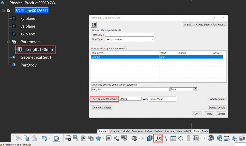
Below is as example of creating a parameter of type length with a value of 0mm.
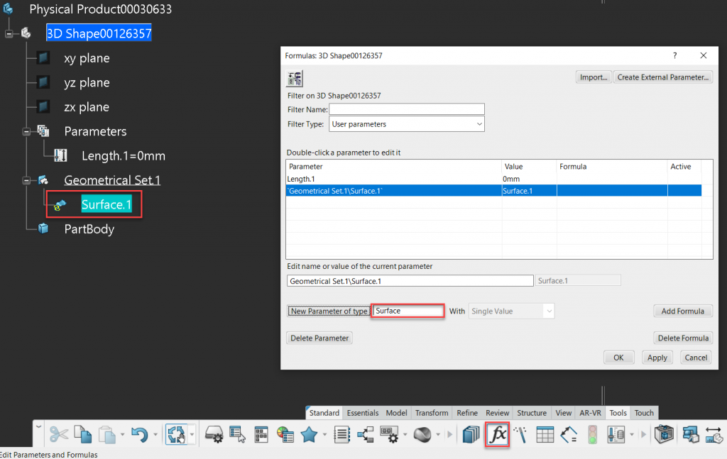
Parameters don’t have to be numeric in nature they can also be geometric in nature, in the case shown below a datum surface with no geometric description can be generated through the same manor. It’s important to understand that since no geometric description has been defined the surface can not be visualized. A simple geometric description could be an extrude, sphere or cylinder, and this description has to be applied either by direct equation Surface1 = Extrude1 or via and object that fully defines the surface.
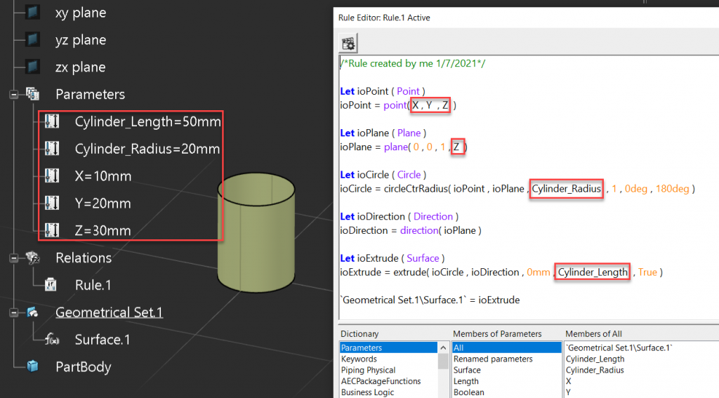
The following code creates a geometrical description for a cylindrical extrude surface. If we think about a cylinder its made from a circle that is extruded along a direction by a value. The circle is defined by a center point, supported by a plane with a given radius. These steps are shown below, we can see that we first define the center point of the circle, then the support plane. The circle can then be defined, which in combination with a direction defines the extrusion. In the very last step we simply equate the parametric surface to extruded surface, this is how the surfaces geometric definition could be defined using a code based object.
/*Rule created by me 1/7/2021*/

Let ioPoint ( Point )
ioPoint = point( 10mm, 20mm , 30mm )

Let ioPlane ( Plane )
ioPlane = plane( 0 , 0 , 1 , 30mm )

Let ioCircle ( Circle )
ioCircle = circleCtrRadius( ioPoint , ioPlane , 20mm , 1 , 0deg , 180deg )

Let ioDirection ( Direction )
ioDirection = direction( ioPlane )

Let ioExtrude ( Surface )
ioExtrude = extrude( ioCircle , ioDirection , 0mm , 50mm , True )

`Geometrical Set.1\Surface.1` = ioExtrude
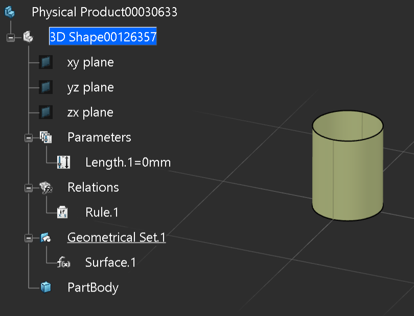
We can now see that the parametric surface has been rendered, this is because the rendering engine knows how to render the object based on its geometrical definition.
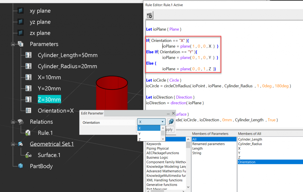
So why would we just not create it through simple geometrical methods? Great Question. in this case its a simple shape but if we combine this with additional user define parameters we can control this parametrically. In the image below we can see that additional parameters have been created and are referenced in the scripting object, instead of hard coded values.
We could take it one step further and add control logic to the scripting object, in this case a simple If Else If block. Allowing the user to change the orientation of the object orthographically.
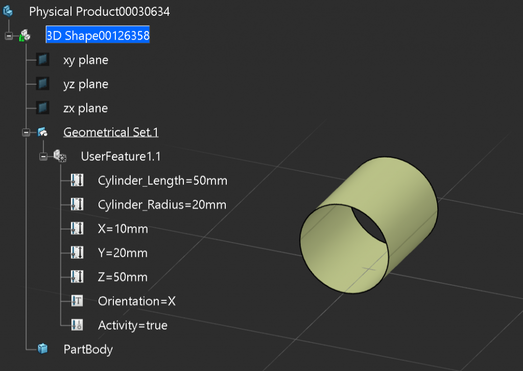
The last step would be to package this up into a custom feature that could be used like any other parametric feature. Typically CAD systems will allow users to create custom features and then publish them into catalogues or add them into custom toolbars so the end user may not even know that its a custom feature. These types of features will auto implement all of the other out of the box coded behaviors, such as cut, copy, paste etc., so the custome user feature will completely behave like any other out of the box feature.
Final Code.
/*Rule created by me 1/7/2021*/

Let ioPoint ( Point )
ioPoint = point( X , Y  , Z  )

Let ioPlane ( Plane )

If( Orientation == "X" ){
	ioPlane = plane( 1 , 0 , 0 , X  )  }
Else If( Orientation == "Y" ){
	ioPlane = plane( 0 , 1 , 0 , Y  )  }
Else {
	ioPlane = plane( 0 , 0 , 1 , Z  )}

Let ioCircle ( Circle )
ioCircle = circleCtrRadius( ioPoint , ioPlane , Cylinder_Radius  , 1 , 0deg , 180deg )

Let ioDirection ( Direction )
ioDirection = direction( ioPlane )

Let ioExtrude ( Surface )
ioExtrude = extrude( ioCircle , ioDirection , 0mm , Cylinder_Length  , True )

`Geometrical Set.1\Surface.1` = ioExtrude