
Table of Contents
Arduino R3 Basic Servo With the PCA9685
In this project were going to see how to connect multiple servos to the PCA9685 breakout board
ref : https://www.youtube.com/watch?v=kUHmYKWwuWs
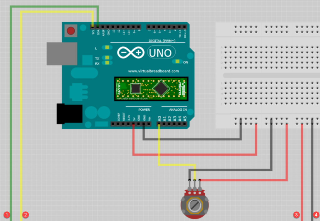
Wiring Diagram
- 1 x Arduino
- 1 x PCA9685 breakout board
- 1 x Servo
- 1 x Variable Resistor or Joystick ( Several Variable resistors)
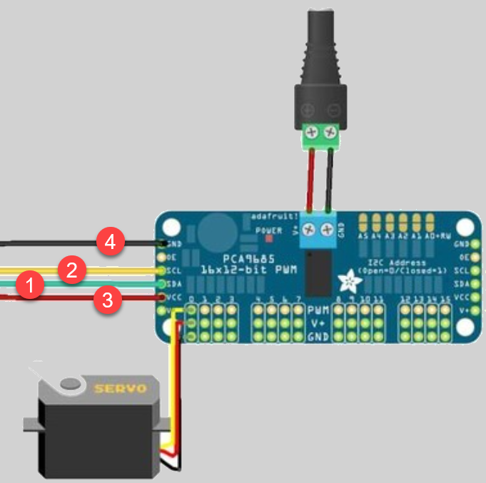
PCA9685
When plugging in the Servo motor connections, the number starts at 0 to 15 from left to right.

Arduino Sketch
The Adafruit PWM Servo Driver library has to be added to the Arduino IDE through the Sketch -> Include Library -> Manage Library’s top toolbar menu.
#include <Wire.h>

#include <Adafruit_PWMServoDriver.h>

#define MIN_PULSE_WIDTH 650
#define MAX_PULSE_WIDTH 2350
#define FREQUENCY 50

Adafruit_PWMServoDriver pwm = Adafruit_PWMServoDriver();

int controlA = A0;

int motorA = 0;


void setup() {
  // put your setup code here, to run once:

  pwm.begin();
  pwm.setPWMFreq(FREQUENCY);
}

void moveMotor(int controlIn, int motorOut)
{
  int pulse_wide, pulse_width, potVal;

  potVal = analogRead(controlIn);

  pulse_wide = map(potVal, 0,1023, MIN_PULSE_WIDTH, MAX_PULSE_WIDTH);
  pulse_width = int(float(pulse_wide)/1000000 * FREQUENCY * 4096);

  pwm.setPWM(motorOut , 0, pulse_width);
}

void loop() {
  // put your main code here, to run repeatedly:

  moveMotor(controlA, motorA);
}